NEMA Wiring Schematic Manual for Electrical Specialists
Nearly seventy percent of the electrical failures within facilities are due to poor wiring practices. This fact emphasizes the necessity of complying with set protocols, underscoring NEMA wiring diagrams’ significance for electrical experts. Via these diagrams, wiring configurations that satisfy both functional effectiveness and highest protection norms are outlined.
The objective of this document is to provide electrical practitioners with deep insights into NEMA criteria. Stressing the importance of correct electrical arrangements is essential. By learning these rules, practitioners can drastically reduce the likelihood of hazards and confirm they meet safety protocols endorsed by Installation Parts Supply. Expertise in NEMA l14-30P wiring diagram is crucial whether developing novel networks or servicing current ones, as it enhances the ability to deliver secure and trustworthy electrical systems.
Key Highlights
- NEMA wiring schematics are essential for guaranteeing electrical security and conformity.
- Adequate wiring methods can reduce electrical malfunctions significantly.
- Comprehending NEMA norms improves the efficiency of electrical arrangements.
- Installation Parts Supply supports following safety protocols in electrical operations.
- NEMA diagrams accommodate a broad spectrum of functions across various sectors.
Grasping NEMA Criteria and Their Significance
NEMA norms are crucial in the electrical field, guiding safety and operation carefully. Crafted by the National Electrical Manufacturers Association, they set pivotal criteria for developing, testing, and identifying electrical gear. This ensures uniformity and dependability across all electrical configurations, which is invaluable.
Identify the NEMA Criteria?
NEMA classifications vary from grades 1 to 13. Every level defines the conditions required for electrical appliances to perform optimally. For instance, NEMA 1 provides basic indoor security but lacks dust shielding. Alternatively, NEMA 4 secures appliances is watertight, a necessity for withstanding significant water exposure. Comprehending these classifications is key in choosing proper appliances.
How NEMA Standards Are Important for Electrical Safety
The impact of NEMA standards in ensuring electrical security is substantial. They play a significant part in reducing shock risks, equipment malfunctions, and fire dangers. Proper adherence to NEMA ratings allows equipment to perform reliably under specific surrounding conditions. For open-air deployment, NEMA 3 classifications offer protection against the elements, shielding the equipment from adverse weather like precipitation and snowfall. In zones at risk of explosions, ratings like NEMA 7, 8, and 9 are critical for maintaining protection.
Uses of NEMA Standards in Wiring Diagrams
The use of NEMA standards in wiring schematics is essential for secure, optimal electrical systems. These diagrams make use of standardized symbols and formats originating from NEMA standards, simplifying the understanding of complex electrical arrangements. This standardizing is helpful. It encourages transparency, standardization, and diminishes confusions, thus improving electrical protection across domestic and commercial environments.
NEMA Wiring Diagram Essentials
NEMA wiring diagrams are vital for electrical professionals, making complicated junctions clear. They describe the connections and elements in diverse installations. By understanding the components, types, and icons of NEMA schematics, technicians can enhance their performance in setups and maintenance.
Elements of NEMA Wiring Schematics
NEMA schematics contain essential components for particular electrical installations. You’ll find wiring terminals, couplers, and additional equipment for safe junctions. Each piece ensures energy is spread efficiently, following security standards.
Types of NEMA Wiring Diagrams
NEMA utilizes various schematics, like linkage diagrams and electrical designs. These schematics outline device associations, while layouts display power flow. Selecting the correct diagram helps with troubleshooting and deployment.
Common Symbols Employed in NEMA Wiring Diagrams
Icons in wiring schematics are crucial for effective conveyance. They illustrate switches, loops, and connectors. Knowing these symbols aids groups interpret drawings correctly. This ensures setups adhere to NEMA norms.
NEMA Wiring Diagram Characteristics
For electrical experts, comprehending the core elements of accurate electrical wiring schematics is crucial. These diagrams bring both clarity and thoroughness, matching setups with NEMA criteria. They demand exact annotation and scaling to reduce installation errors. This fosters a protected and highly efficient workplace.
Key Attributes of Accurate Electrical Wiring Drawings
Precise electrical wiring schematics are indispensable in electrical projects. They encompass crucial qualities such as:
- Clarity: Drawings must be unambiguous, minimizing misinterpretation risks.
- Wholeness: They should incorporate all key elements, junctions, and electrical standards.
- Standard Compliance: Adherence to NEMA norms is non-negotiable for securing security and performance.
- Detailed Labeling: Distinct markings on each element are crucial for comprehension and avoiding mistakes.
- Proper Sizing: The dimensions should reflect the actual setup to portray the configuration accurately.
Understanding NEMA Coupler Configuration
The insight into NEMA coupler pinout is crucial for forming proper linkages in electrical setups. Awareness of particular pin setups upholds safety and equipment operation. There is a variety of NEMA connectors, intended for different power levels and flows, encompassing:
| Connector Model | Ampere Rating | Voltage Level |
|---|---|---|
| L5-15 | 15A | 125V |
| L5-20 | 20A | 125V |
| L14-20 | 20A | 125/250V |
| L1430C | 30A | 125/250V |
| L620C | 20A | 250V |
| L1430C | 30A | 125/250V |
| L630R | 30A | 250V |
Comprehending NEMA coupler configurations is essential for reliable linkages, enhancing performance. It’s critical to match interfaces with equipment properly using twist-lock or flat blade styles, to dodge safety risks.
NEMA Device Wiring
NEMA device wiring includes various setups for protected electrical device linkages. These standards guarantee that devices work together reliably, reducing hazard. Knowing the various NEMA appliances and their wiring is crucial for specialists.
Different Kinds of NEMA Units
NEMA classifies appliances by type based on power levels and current requirements. Primary setups are:
- 2-Pole 2-Wire
- 2-Pole 3-Wire Grounding
- 3-Pole, 3-Wire
- 3-Pole, 4-Wire with Grounding
- 4-Pole, 4-Wire
- 4-Pole 5-Wire Grounding
These setups are employed in residences and industrial facilities, supporting 125V, 208V, and 480V.
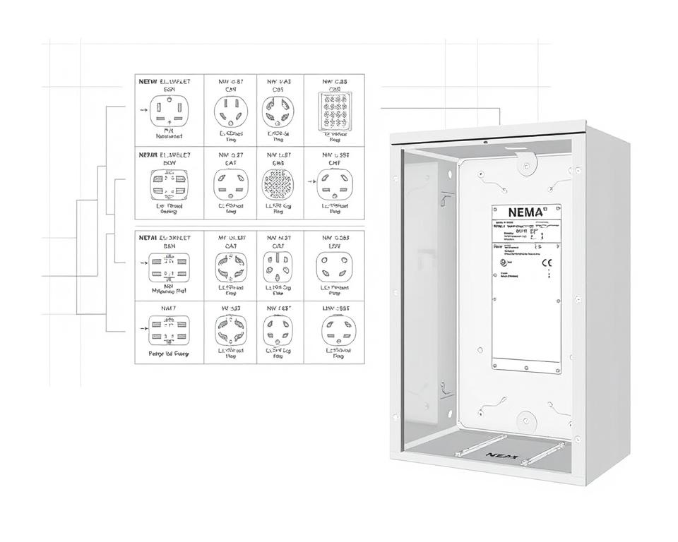
NEMA Outlet Wiring Outlined
NEMA plug wiring differs to meet multiple electrical demands, with twist-lock types providing secure connections in vibrating settings. For example, the L5-15 plug is rated for 15 amperes, common in business sites, whereas the L14-20 is designed for 20 amps at 125/250 voltage.
The NEMA naming scheme assists in choosing the appropriate plugs, spotlighting characteristics like charge orientation and connection to ground. This precision guarantees that devices operate securely.
NEMA Outlet Wiring Standards
Correct wiring of NEMA receptacles meets electrical codes and security protocols. For example, L530R receptacles are rated for 30 amps at 125 voltage, with L630R variants for 250 voltage. Correct grounding is essential to avoid electrical mishaps.
Choosing approved NEMA plugs and outlets secures secure, regulation-compliant setups. It’s critical to consult authoritative standards when installing.
NEMA Motor Wiring and Implementations
NEMA motor wiring is essential in electrical engineering, particularly for commercial use. Knowing how NEMA motor arrangement works secures that motors are set up for peak efficiency. Such devices, like single-phase and three-phase models, require accurate wiring to work safely and efficiently.
Summary of NEMA Motor Wiring
Understanding NEMA motor wiring requires understanding of connections and configurations. Most three-phase motors are compatible with dual-voltage, signifying they can work on both low (208-230V) and high power levels (460V). Wiring at high voltage allows motors to draw less current than at low voltage. High voltage advantages encompass reduced gauge wiring for the input, a notable benefit for motors exceeding 10 HP.
While both NEMA and IEC appliances are utilized in the market, NEMA models are generally larger and priceier than IEC ones for below 100 HP uses. NEMA controllers vary from size 00 to 9, appropriate for various uses. A standard feature in NEMA trips is a Trip Rating of 20, engineered to trigger when a motor’s draw surpasses 6-fold the Full Load Amperage in 10 seconds.
Opting for the Appropriate NEMA Motor Setup
Selecting the appropriate NEMA motor arrangement influences overall performance and safety. A typical three-wire control circuit employs three wires for a start/stop pushbutton panel, facilitating simple motor operation. Frequent three-phase configurations consist of the 12 Lead Dual Voltage and 6 Lead, facilitating Wye and Delta connections.
IEC motor starters often include phase failure detection, enhancing safety. They also offer configurable Trip Ratings for tailored protection in low power operations. Furthermore, many models have temperature safeguards, critical for single-phase and Dual Voltage systems.
| Setup Type | Voltage Type | Current Rating | Typical Use |
|---|---|---|---|
| 12 Lead Dual Voltage | Dual Voltage (208-230V / 460V) | Motor size dependent | Applications with Wye Start and Delta Run |
| 6 Lead | Single/Dual Voltage | Up to 32 amps | Wye/Delta configurations |
| Single Phase | One Voltage | Ranges from 1 to 5 amps | Two Speed, Two Winding applications |
| Delta Connection | Elevated Voltage | Depending on setup | Various applications including Current Transformers |
The Bottom Line
Grasping NEMA wiring drawings and criteria is crucial for electrical professionals seeking to improve their capabilities and adhere to electrical safety standards. These guidelines secure safe and effective electrical configurations but also avert dangers associated with incorrect wiring. As discussed, complying with NEMA norms leads to the enhanced capability of diverse NEMA devices and setups.
For technicians, the selection of superior supplies can profoundly influence the result of their work. Installation Parts Supply provides a wide selection of wiring items in accordance with NEMA criteria. This empowers specialists to access critical parts for fulfilling these important regulations. High-quality resources and deep expertise of NEMA wiring diagrams greatly enhance project security and performance.
During electrical deployments, always place safety and accuracy as a priority. Becoming well-versed in NEMA criteria offers the knowledge required to executing optimal procedures correctly. This secures that every electrical connection made meets premium norms.
Common Questions
Identify NEMA wiring drawings?
NEMA wiring diagrams showcase the configurations and junctions of NEMA-standard electrical appliances. They adhere to safety and functional norms established by the National Electrical Manufacturers Association.
What makes NEMA norms vital for electrical security?
NEMA criteria are fundamental to defining safety and performance benchmarks for electrical devices. These principles assist electrical experts minimize electric shock, equipment failure, and fire hazards.
Which elements are crucial in a NEMA wiring schematic?
Fundamental parts in a NEMA wiring diagram comprise electrical layouts and linkage diagrams. These schematics also feature thorough annotations and show the electrical system’s various parts precisely for setups.
Which kinds of NEMA wiring diagrams are used?
Various NEMA wiring diagrams serve various applications, including circuitry for power distribution and interconnection diagrams for components. Every design plays a unique role in electrical systems.
Identify the common symbols employed in NEMA wiring drawings?
Common symbols in these diagrams symbolize toggles, interruptors, outlets, and additional components. Use of these symbols encourages unambiguous interaction and accurate understanding of wiring drawings.
Identify the essential attributes of precise electrical wiring diagrams?
Precision in electrical wiring drawings is defined by their clarity, comprehensiveness, and explicit labeling. They must align with NEMA standards to prevent faults in setup.
Explain a NEMA connector configuration?
A NEMA connector pinout depicts electrical linkages at a connector, showing particular pin roles. This secures secure and effective junctions in electrical setups.
Which are the various kinds of NEMA units?
NEMA appliances include various electrical receptacles and couplers, like plugs and outlets. They are crafted for diverse amperage and voltage levels criteria to satisfy specific operational demands.
In what way is NEMA plug wiring arranged?
NEMA plug wiring depends on particular amperage and voltage needs, following safety standards and electrical codes for multiple electrical uses.
What guidelines are there for NEMA outlet wiring?
Guidelines for wiring NEMA outlets emphasize following electrical regulations, guaranteeing accurate charge alignment, and picking correct wire sizes. This ensures both security and performance in electrical configurations.
How can I wire a NEMA motor properly?
To set up a NEMA motor, one must understand its defined single-phase or tri-phase setup. Choosing the right wiring technique is crucial, plus maintaining electrical protection for optimized motor efficiency.
Which factors should be considered when selecting a NEMA motor setup?
Opting for a NEMA motor setup demands an assessment of the project’s power needs and performance traits. It’s also essential to ensure compatibility with existing machinery for guaranteed performance and safety.